Five-Layer Safety in Practice
Safety in a distributed system is a stack of measures: cell, module, system, network and fire linkage. Each layer covers a failure the others cannot.
Key takeaways
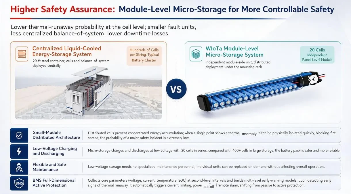
Layer one: the cell
Cell selection sets the baseline. Lithium iron phosphate chemistry is chosen for thermal stability and cycle life, and each rod holds a limited number of cells in series. A small cell count per enclosure means a lower stored energy per node and reduced pack-level stress, which is the foundation everything else builds on.
Layer two: the module
Each enclosure carries its own battery management system, sampling voltage, current, temperature and state of charge on a short interval. Multi-level warnings trigger limits on current, cut power locally and raise an alarm remotely. Because management is per module rather than per fleet, a developing problem in one unit is visible before it can influence neighbours.
Layer three: the system
At system level, protection covers over-voltage, under-voltage, over-temperature, lightning and reverse current, with an anti-reverse-current device included in the architecture. The electrical design keeps voltage low on the DC side of the retrofit and preserves the plant's existing protection coordination instead of disturbing it.
Layer four: the network
The wireless mesh makes faults locatable. Precise device addressing, per-unit status and event logs mean a maintenance team receives an identifier rather than an area. Knowing which unit and which row, at which time, changes a search into a single swap, and it produces the record trail that incident reviews require.
Drills and response time
A linkage is only as good as the response behind it. Run an annual exercise: trigger a test alarm, confirm the platform reports it, confirm the fire system receives the signal, and measure how long the on-call engineer takes to acknowledge. Documenting that timing gives the operator something concrete to report to insurers and to their own management.
Extending a layer over time
Layers are added as a fleet matures. Early sites may have per-unit monitoring and local alarms; later they gain automated linkage, historical analytics and firmware-wide improvements. Because the platform is common across sites, an improvement developed for one plant can be applied portfolio-wide, which is a genuine advantage of keeping the monitoring layer consistent.
How layers map to standards
Each safety layer answers a requirement that appears somewhere in a standard or a code: equipment safety certification for the hardware, rapid shutdown requirements for the system behaviour, battery standards for the storage stage, and environmental ratings for field mounting. Mapping the layers to the applicable clauses gives a technical reviewer a fast way to see coverage instead of reconstructing it from a feature list.
Layer five: fire linkage
The platform can link to site fire systems, triggering tiered responses: cut power, isolate or cool the affected circuit, stop associated equipment and notify the responsible team. Dispersed geometry supports this layer directly, since separated small nodes give a response system time and space to work, and reduce the chance that one event affects a large part of the plant.
Want this analyzed for your plant?
Send your array data and we will return a technical view within one business day.
Literature search entries on Five-Layer Safety & DC Arc Rapid Shutdown
The entries below open literature search results rather than single papers, so the reading list can be filtered by date, citation count and full-text availability at the source. 24 queries across five indexes, grouped by source.
Google Scholar1
Semantic Scholar1
Baidu Scholar1
IEEE Xplore1
ScienceDirect1
OpenAlex19
- DC arc fault detection photovoltaic rapid shutdown
- lithium ion battery thermal runaway propagation
- PV DC arc fault protection standard
- distributed battery system safety design
- rapid shutdown device NEC requirements
- battery protection circuit PV
- arc fault circuit interrupter DC
- PV rapid shutdown UL3741
- thermal runaway prevention lithium battery
- system safety certification photovoltaic
- DC arc detection algorithm
- overcurrent protection PV system
- insulation monitoring DC microgrid
- lithium iron phosphate safety tests
- ground fault protection solar array
- battery thermal management design
- UL 9540 energy storage safety
- NEC 2017 rapid shutdown
- spark detection photovoltaic system
Take the Numbers With You
The brochure covers the storage rod, the five safety layers, the gateway and the cloud platform. Download it, or send us your site conditions for a proposal within one business day.