Line Loss and Circulating Current on the DC Side
Short distances and a single voltage domain reduce two quiet losses that a distant battery room quietly introduces into every cycle.
Key takeaways
- Every metre of conductor adds resistance, and resistive loss scales with the square of current.
- Some layouts force longer conductors, for example where a battery room already exists or where a retrofit must connect at a collector point.
- Keep DC runs short, minimize parallel source paths, avoid unnecessary voltage translation, and prefer architectures that put storage where the energy is produced.
Losses that scale with distance
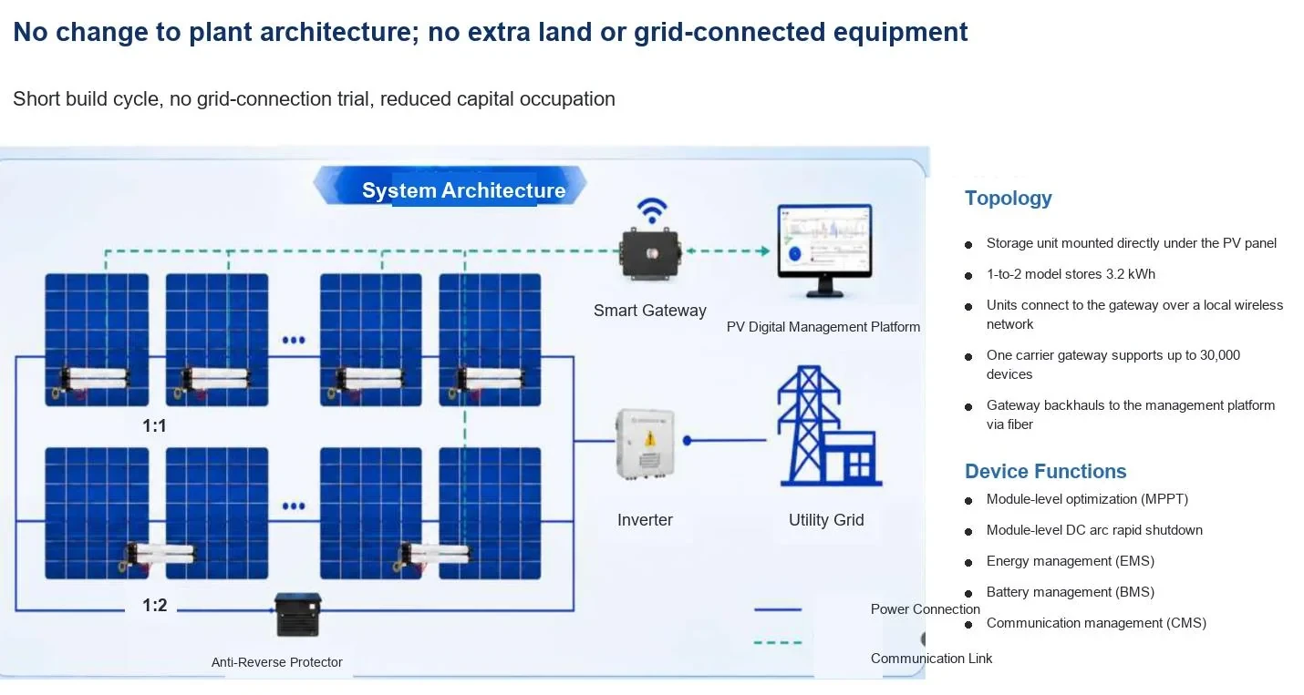
Every metre of conductor adds resistance, and resistive loss scales with the square of current. A battery room a hundred metres from the array therefore pays a penalty on every charge and discharge cycle, in both directions. Placing storage directly beneath the modules shortens the electrical path to a few metres and removes most of that penalty.
Circulating current
Where multiple sources feed a common bus with slightly different voltages, currents circulate between them without doing useful work. The effect is subtle but persistent: it warms conductors, consumes energy and complicates measurement of true round-trip efficiency. Keeping storage distributed and locally regulated limits the parallel paths that create it.
Voltage drop and operating windows
Long DC runs also consume voltage headroom. On the AC side, transformers and cabling introduce their own drops. Both effects shrink the window in which the system can operate efficiently, particularly at low irradiance when voltage margins are tight. Short, low-voltage connections keep the operating window wide.
Measuring rather than assuming
Calculate losses from actual cable lengths, cross-sections and expected currents before the design is fixed, then verify them during commissioning with clamp meters on both ends of the run. On retrofit projects, documenting the comparison against the pre-retrofit state is often what convinces an owner that the change is real.
When the run cannot be short
Some layouts force longer conductors, for example where a battery room already exists or where a retrofit must connect at a collector point. In those cases, increase cross-section rather than accepting the loss, and model the cost of the copper against the energy it saves over the asset life. The calculation is straightforward and it usually favours larger cable.
Verifying during commissioning
Measure current and voltage at both ends of each representative run during commissioning, compute the loss as a percentage, and compare it with the design assumption. Where a run exceeds the assumption, document why and record it for the O&M file. That record is what makes later performance discussions factual rather than speculative.
Grounding and shielding considerations
Adding powered electronics in the field changes the plant's grounding picture, particularly on arrays with long rail runs and multiple earthing points. Confirm how the device is bonded, how signal and power paths are routed relative to lightning protection, and whether the existing scheme needs review. Lightning protection is a stated product feature, but its effectiveness depends on the installation it is connected to.
Practical design rules
Keep DC runs short, minimize parallel source paths, avoid unnecessary voltage translation, and prefer architectures that put storage where the energy is produced. None of these rules is exotic; applied together, they explain why distributed storage on the DC side can outperform a nominally better battery that sits a cable run away.
Want this analyzed for your plant?
Send your array data and we will return a technical view within one business day.
Literature search entries on Efficiency, Cost & Core Advantages
The entries below open literature search results rather than single papers, so the reading list can be filtered by date, citation count and full-text availability at the source. 24 queries across five indexes, grouped by source.
Google Scholar1
Semantic Scholar1
Baidu Scholar1
IEEE Xplore1
ScienceDirect1
OpenAlex19
- round-trip efficiency DC coupled vs AC coupled storage
- comparison AC side storage DC side storage efficiency
- levelized cost of energy solar PV storage
- photovoltaic mismatch loss module-level MPPT
- energy storage thermal management power consumption
- storage round-trip efficiency optimization
- PV battery system cost reduction
- capacity degradation PV storage
- photovoltaic storage payback analysis
- mismatch losses mitigation PV
- energy storage round trip AC DC
- PV self-consumption rate battery
- economic benefits distributed storage
- heat losses power electronics PV
- availability factor solar storage
- lcoe comparison AC DC coupled
- photovoltaic battery efficiency measurement
- internal rate of return solar storage
- operating cost PV battery system
Take the Numbers With You
The brochure covers the storage rod, the five safety layers, the gateway and the cloud platform. Download it, or send us your site conditions for a proposal within one business day.